

How to Build a Roll-Off Roof Observatory: The Complete DIY Guide
A step-by-step guide to building a DIY roll-off roof observatory — slab and pier design, wall framing, roof mechanisms, meridian flip clearance, weather sealing, and roof automation — from people who build roof drive systems for a living.
A roll-off roof observatory is the most practical permanent home for a telescope that most amateurs will ever build. Your mount stays polar-aligned, your cables stay connected, and "going observing" turns into "roll the roof back and start imaging" instead of an hour of setup and teardown. And unlike a dome, a roll-off roof (often abbreviated RoR) is fundamentally carpentry — if you can build a shed, you can build one.
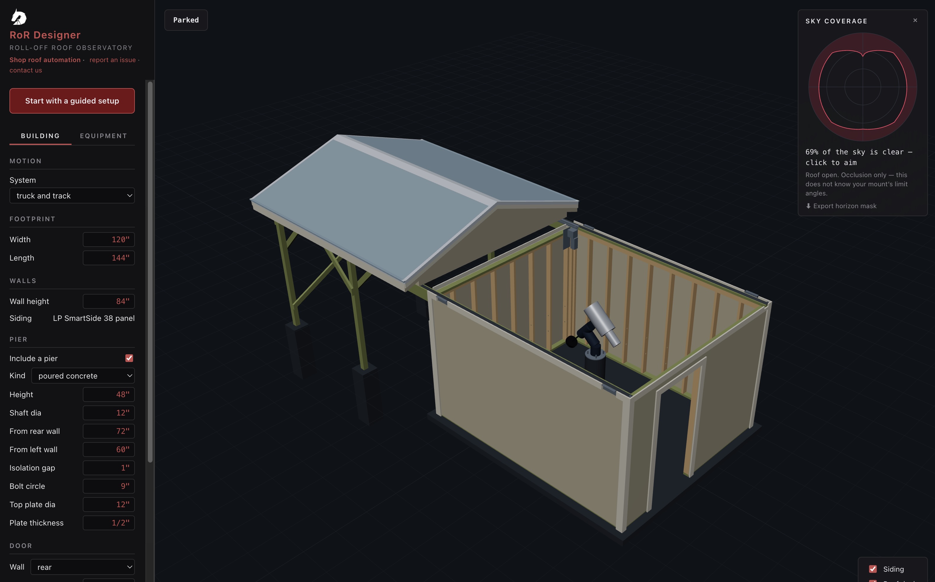
The process of designing and building a roll-off roof observatory can be daunting at first. That's why we built RoR Designer — a free tool that lets you model the observatory the way you want it, checks along the way for common problems, and gives you a step-by-step build plan to follow. The guide below provides general instructions and reasoning behind each step. The designer provides true step-by-step instructions.
But here's the thing this guide exists to tell you: a roll-off roof observatory is not a shed. It's a shed-shaped machine with one large moving part, and two design decisions determine whether that machine works or whether you end up rebuilding walls after the concrete is poured. We'll cover those first, then walk the full build in order — the same stage sequence we use in our own build plans: pier and slab, walls, roof mechanism, trim and door, the rolling roof carriage, deck and skirts, roofing, drive rack, weather seal, solar shield, and paint and caulk.
Why a Roll-Off Roof Instead of a Dome?
A dome protects the scope from wind and stray light, but it costs more, it's harder to build well, and the slit has to track the telescope all night. A roll-off roof opens the entire sky at once: no rotation motors, no slit synchronization, no shutter geometry. For astrophotography — where the mount slews between targets and does a meridian flip in the middle of the night — that "whole sky at once" property is a genuine advantage, not just a cost savings.
The trade-off is that an RoR building exposes the scope to wind and requires walls low enough to see over. Which brings us directly to the decisions that make or break the design.
The Two Decisions That Make or Break the Build
Get these two right on paper and the rest of the build is straightforward framing. Get them wrong and no amount of good carpentry saves you.
Decision 1: Roof travel clearance — including the meridian flip
When the roof rolls open or closed, its lowest structural member — the bottom of the rafters, rafter ties, or the carriage rails themselves — sweeps a horizontal plane across the entire building. That plane rides just above your wall tops, and everything attached to your pier must fit below it while the roof is moving. The decision is what "everything" has to mean for your build.
Here's why that's a real question. If you run a German equatorial mount (GEM — the common mount style where a counterweight bar balances the telescope across the polar axis), the telescope doesn't occupy one position: the tube can point anywhere in the sky, the counterweight bar tracks it on the opposite side of the polar axis, and a meridian flip rotates the whole assembly from one side of the pier to the other as a target crosses due south. Over a night, all of that sweeps out a volume far larger than the scope itself — and its highest point is usually not the position people eyeball. It's typically the counterweight-down, pole-pointed home position, where the tube sits at its steepest angle off the mount head. Whether your roof has to clear that whole volume, or only a parked scope, is the actual decision:
- Design the roof to clear only the parked scope, and interlock the roof so it can't move unless the mount is parked — what's often called an interference fit, since the scope interferes with the roof's travel whenever it isn't parked. Notice what this option never has to clear: the swept volume. The mount only moves through it at night, with the roof already open, so the meridian flip asks nothing of the building. A parked mount is a single compact shape — most mounts let you define the park position, so you choose a low one — and that's why builders pick this option: the pier can stand taller under the same roof, lifting the telescope relative to the walls so it can work closer to the horizon. The cost is that your roof controller and mount software must actually enforce the interlock — when clouds roll in at 3 a.m., the roof has to wait for the mount to park before it closes, and a roof that closes onto an unparked telescope is the most expensive mistake in this hobby.
- Design the roof to clear the full swept volume, so the roof can move no matter what the mount is doing. This is the option where the sweep drives the design: the whole volume, home position included, has to fit under the travel plane, and in exchange the roof can close immediately on a rain sensor without asking the mount's permission first — the safer architecture for remote and automated operation. When the sweep doesn't fit, the fix is to shorten the pier, not to raise the walls or gables — pier height is the variable that moves your equipment down relative to the travel plane. The trade is a lower telescope behind the same walls, which costs you low-altitude sky; that tension is what Decision 2 is about.
Either way, do the geometry before you buy lumber, against whichever envelope you chose. For an interference fit, that's the parked scope's highest point; for full clearance, it's pier height, plus mount base-to-saddle height, plus the longest radius the tube and counterweight bar sweep around the mount's axes — compared against the height of the lowest roof member above the floor. This is exactly the problem our free RoR Designer tool exists to solve — you model the building in 3D, drop in your actual pier, mount, and telescope, and it checks roof clearance through a full meridian flip before anything is cut. Ten minutes in a planner is cheaper than reframing a wall.
Decision 2: Wall height vs. horizon visibility
With the roof open, your walls are your horizon. From the telescope's position, the sky obstruction angle at any compass bearing is simple trigonometry: the height of the wall top above your optical axis, divided by the horizontal distance to that wall, run through an arctangent. Closer walls and taller walls block more sky; a scope sitting near one wall of a small building can lose 30 degrees or more of altitude in that direction.
So low walls are better, right? Partly. Lower walls block less sky — but the roof travel plane rides on the wall tops, so lowering the walls lowers the plane, and the same clearance rule from Decision 1 forces the pier down with it. Your optical axis drops nearly in lockstep with the wall tops, your eyepiece or camera ends up closer to the floor, and much of the obstruction angle you meant to shrink comes right back. Lower walls also mean the roof structure itself has to carry more of the height budget: on a gabled roof, the travel plane sits at the eave line, so a low-walled building often needs a taller, steeper roof to buy back interior clearance. There is a real optimization here, not a single right answer.
A few practical anchors from real builds:
- Wall height has a practical floor as well as a sky-blocking ceiling. You need headroom to walk around inside with the roof closed, and a standard pre-hung exterior door needs roughly a 6'10" rough opening. Build shorter than that and you give up off-the-shelf doors and the ability to stand up straight with the roof shut, in exchange for less sky blocked when it's open — most builders don't go below what a stock door and real headroom require.
- Prioritize the horizon that matters. In the northern hemisphere, your best imaging happens toward the south, and the celestial pole sits at an altitude equal to your latitude — comfortably above a modest wall for most of the US and Canada. Many builders roll the roof off to the north for exactly this reason: the parked roof stack only shadows low northern sky.
- A fold-down wall panel on the south side is a proven trick: frame a section of the south wall as a hinged panel that drops open for observing and latches shut (and seals) for weather. You keep weather protection at full height and observing access at half height.
RoR Designer shows the blocked-sky altitude at every compass bearing for your actual scope position, which turns this from guesswork into a decision you can see.
With those two decisions settled, here's the build, stage by stage.
Before You Start
Check your permit situation first. Many jurisdictions exempt accessory buildings under a size threshold (often 120 square feet) from permits, but rules vary widely, and a structure with electrical service usually needs an electrical permit regardless. A quick call to your building department beats a stop-work order.
Pick the site deliberately. You want reasonable horizons in your priority directions, distance from neighbors' security lights, ground that drains (never the low spot in the yard), and a plan for power and network — either a practical trench route back to the house, or an off-grid setup with solar, batteries, and wireless networking (cellular, satellite, or local WiFi) if trenching isn't an option. Stand at the proposed pier location at night before you commit.
Size the building around the swept volume, not the floor plan. A 10×12-foot building is a comfortable single-scope size with room to walk around the pier; 8×8 works but gets tight fast once a GEM starts swinging. Decide your roll-off direction now, because it drives the slab, the wall layout, and (for track-style roofs) a support structure that extends beyond the building.
Choose your roof mechanism now, too — drawer-slide or track-and-truck (covered below) — because the two styles diverge right after the walls go up.
Slab — and Why Your Pier Never Touches It
Pour a standard reinforced slab for the building: 4 inches is typical, with a thickened perimeter or frost footings per your local frost depth, and anchor bolts set in the wet concrete to receive pressure-treated sill plates. Get the slab flat and level — the walls inherit every error, and the roof mechanism inherits the walls' errors.
The part that separates an observatory slab from a shed slab: the telescope pier gets its own foundation, structurally isolated from the slab — and the pier goes in first. Dig below frost depth, pour a footing pad and a sonotube column as one piece with no construction joint, and let it cure before the slab is poured around it: sleeve the pier when you form the slab so the concrete stops about an inch short of it all the way around, then fill that gap with compressible expansion-joint filler and a flexible sealant cap — never grout, mortar, or rebar crossing it — dressed with a trim ring later. The reason is vibration. When you walk across the slab at 2 a.m. to check a cable, an isolated pier doesn't care; a pier tied into the slab prints your footsteps into every sub-exposure.
Two things must happen before concrete: sink J-bolts or a bolt template for your pier's base plate into the pier footing, aligned so the mount can reach true north with its azimuth adjustment range, and stub up conduit into the pier area for power and data. Retrofitting conduit through cured concrete is nobody's favorite weekend.
Walls: Framing for a Roof That Moves
Frame the side walls and end walls as conventional stud walls on pressure-treated sills — with three departures from shed practice. (One habit worth stealing from our build plans: frame each wall flat on the ground outside the building, square it by its diagonals, and walk it up onto its line — the pier is already standing finished in the middle of the slab, so there's no clear floor in there to frame on.)
First, the side walls parallel to roof travel carry the mechanism — but don't overthink the precision. This isn't instrument-grade tolerance; it's carpentry. Mount the running surface as adjustable angle-iron rail on top of the wall plates, with the angle set (and squared for parallel between the two sides) after the walls are framed and before it's screwed down, rather than trusting the lumber to be perfectly straight on its own. Pair that with V-groove wheels on the roof carriage, and a small hump or dip in the top plate is a non-event — a decent roof motor and controller handles the extra resistance without noticing. (That forgiveness belongs to the track-and-truck style; ball-bearing drawer slides are far less tolerant of a bowed wall — more on that in the mechanism section below.)
Second, nothing on any wall may rise into the roof's travel path. On a shed, the end walls continue up into gable triangles. On a roll-off roof, they can't — the roof has to pass over them. Every fixed wall frames flat-topped, but the wall tops are not all at the same elevation, and the two mechanism styles handle it differently. On a track-and-truck build, all four walls frame to the same height, and then the two side walls get an extra third track plate that raises the running surface above the end-wall tops — that step is what lets the rolling truck, and the drive rack hanging below it, sweep over the end walls with clearance; the gable triangles travel with the roof as part of the rolling carriage (more on that below). On a drawer-slide build, the side walls carry the slide plates, and the roll-off end wall actually frames an inch and a half lower than the rest so the roof-borne gear rack can sweep over its plates. Either way the rule holds: frame the fixed walls flat-topped and resist the instinct to build gables onto them.
Third, think about racking. The walls lose the roof diaphragm that normally stiffens a shed whenever the roof is open. Sheath the walls fully — either structural sheathing under the siding, or a rated structural panel siding that does both jobs in one layer, nailed on the schedule that earns its bracing rating — so they brace themselves.
Choosing a Roof Mechanism: Drawer-Slide vs. Track-and-Truck
There are two proven families of roll-off mechanism, and your building size largely picks between them.
Drawer-slide style: the roof is a drawer
In a drawer-slide roof, the roof literally rides on a pair of heavy-duty full-extension ball-bearing drawer slides — the same hardware as a toolbox drawer, scaled up to units rated for hundreds of pounds per pair. Each side wall gets a slide plate: a pressure-treated 4x4 laid flat on the wall cap, thick enough that every mounting screw lands in solid wood. The slides mount to the plates' outside faces over full-length aluminum backer bars — framing lumber is never furniture-straight, and a bow the eye can't see will bind a ball-bearing slide, so the bar bridges it. The slides' moving members bolt to the roof's carriage rails, and the roof deck itself becomes the diaphragm that keeps the two slides parallel for good. Think of the whole building as a drawer: the walls are the cabinet, the slides are the runners, and the roof is the drawer.
It has fewer parts than a track-and-truck build, and nothing extends past the building footprint — but don't mistake that for simple. The two slides have to run almost perfectly parallel or they bind, travel tops out around 60 inches even in the best case, and the roof has to be pushed or driven from the centerline: push it off-axis and you torque one slide against the other instead of moving the roof. The honest limitations are travel and weight: the roof can only open as far as the slides extend, and the whole moving roof has to stay inside the slides' load rating, so this is the system for small buildings with light, low-slope roofs. For a compact backyard observatory, it's often the right answer precisely because there's less to build — even though what there is has to be built and driven carefully.
Track-and-truck style: for longer travel and heavier roofs
A track-and-truck roof rides on a truck — a rolling chassis of doubled rails and framed ends with V-groove wheels bolted through it — running on V-track mounted along the tops of the two side walls (the track walls, in our plans' language). Because the roof rolls clear of the building, the track continues beyond it on an outrigger: posts set below frost depth, beams hung off the building's corner framing, and a cap that carries the rail line dead flush and level with the wall plates, knee- and cross-braced so it stays straight under the parked roof's full weight, in wind, for years. The truck goes together on the track itself, and there's a trick worth knowing: leave the track fasteners out at first, roll the assembled truck back and forth, and let the V-grooves pull both runs exactly parallel at the real rolling gauge — then screw the track down. The truck trues its own track better than any tape measure.
This is the system for longer buildings, heavier roofs, and full roll-off travel where the entire sky opens up. It's more construction — you're effectively building a short elevated railroad — but the rolling effort is lower and the capacity is far higher: a well-built truck moves a half-ton roof with about twenty pounds of push. Whichever style you build, the acceptance test is the same: one person should be able to move the roof smoothly by hand, with no bind points anywhere in the travel. If it takes a shoulder, find the high spot now, not after the roofing is on.
Exterior Trim and the Door
Trim out the fixed walls before the roof goes on — corner boards, fascia on the fixed structure, and the trim details that close up the sheathing edges. It's far easier now than working around a rolling roof.
Hang the door at this stage too. An out-swing door with a proper threshold and weatherstripping is the standard choice; it doesn't eat interior floor space in a small building, and in snow country you'll appreciate a door that doesn't have to plow the floor. (On a very low-walled mini build, no stock door will fit — a site-built Z-braced plank door skinned in the same siding is the classic answer.) Put it in a wall that doesn't carry the mechanism if your layout allows.
Roof Framing: Building the Rolling Carriage
Here's the mental shift: you are not framing a roof, you are building a rolling carriage that happens to be roof-shaped. A conventional roof borrows stiffness from the walls it's nailed to. Yours is nailed to nothing. It must resist racking, twisting, and wind loads entirely on its own, while staying light enough to move.
What the carriage looks like depends on the mechanism. On a track-and-truck build, the truck is the base of the carriage: doubled side rails with the wheels bolted through them, closed by solid multi-ply end frames, squared by its diagonals on the track, stiffened with flat 45° corner braces, and capped with wider stock that becomes the roof's bearing surface. Rafters birdsmouth onto those caps, a ridge board ties them at the peak, rafter ties across the building keep the roof's spread from bowing the rails apart, and the gable triangles are framed into the roof ends — bevel-topped studs under the end rafters — since the fixed walls below stop flat. On a drawer-slide build, the carriage is simpler and has no gables at all: two tapered rails (each one doing triple duty as drawer side, fascia, and slide weather shield) with flat joists between them, the taper itself providing the shallow roof pitch. Either way, one rule is absolute: the roof frame fastens to the rolling carriage only, never to the walls — a single fastener from roof to wall means it will never roll again. When the sheathing goes on, the carriage becomes a proper stiff box; square it by its diagonals before the first sheet locks in whatever shape it finds.
Weight discipline matters at every choice here. Every pound of roof is a pound your arms — or your drive motor — moves twice a night, and a pound of wind-day momentum your end stops absorb. Frame adequately, not extravagantly, and save weight for where it counts.
Plan for end stops and hold-downs too. Positive mechanical stops mount on the track just past each end of travel, and hold-down hardware — interlocking angle pairs at the corners of a bigger roof, draw latches on a small slide-off — goes on once the roof is rolling, locking the closed roof to the fixed walls. Neither is optional. A closed roll-off roof is a wing; wind uplift on an unlatched roof has relocated more than one of them into a neighbor's yard.
Roof Deck, Sheathing, and Skirts
Sheath the roof deck as you would any roof — and remember that on a drawer-slide roof the deck is doing structural double duty as the diaphragm that keeps the slides parallel, so square the carriage immediately before the first sheet goes on, and roll the roof through its full travel after every sheet. Then add the detail that makes the moving joint work: skirts — panels hung on the carriage faces, reaching down past the carriage rails to close off the roll band, the open horizontal slot between the moving roof and the fixed wall tops.
The skirts do two jobs. Structurally, they close the box and stiffen the carriage. Weather-wise, they're half of a labyrinth: the carriage overhangs the walls, so water running off the roof drips at the skirts, outside the walls, instead of finding the gap — and the slot that remains gets baffled closed in the weather-seal stage, not sealed by contact. This is the core weatherproofing insight of the whole building — where a roof has to move, you shed water by overlap, overhang, and gravity, never by caulk or compression alone. The skirts must sweep clear of the siding and trim below through the full travel — sight the gap before the roofing goes on.
Roofing
Any conventional roofing works, but the scale tips toward light. Metal panel roofing is the popular choice for RoR builds for good reasons: it's a fraction of the weight of asphalt shingles, it goes on fast over underlayment on the solid deck (which the carriage needs for stiffness anyway), and it sheds snow. Shingles work on truck-borne roofs that are sized for the weight, but you're adding several hundred pounds to a moving assembly — make that choice deliberately, not by default.
One caveat for near-flat slide-off roofs: a half-inch-per-foot pitch is below the rating of every shingle and screw-down metal panel, so slope alone won't keep it dry. Cover the whole deck with self-adhered membrane first and treat the metal as armor over it — the membrane is the real roof.
Whatever you choose, flash and detail the ridge and edges as if the roof were fixed. The moving joint is handled by the skirts and seals; the roof surface itself should be boringly watertight.
Drive Rack: Manual Push or Motorized Roof
Plenty of observatories run for years with a hand-pushed roof, and if your mechanism is built right, that's a one-hand job. But the moment you want to image from the couch, close up automatically when clouds roll in, or run the observatory remotely, the roof needs a motor and a controller that knows what it's doing. Install the drive only after the roof rolls clean by hand — a motor hides binding problems until they break something.
The standard architecture is a drive rack: a gear rack mounted along the roof carriage, driven by a pinion on a gearmotor fixed to the building (or the mirror arrangement). Rack-and-pinion drive gives positive engagement in both directions — it can't slip like a friction wheel or go slack like a cable — and the gear reduction holds the roof in place when the motor is off. Pair it with limit switches at both ends of travel so the controller knows, electrically, when the roof is fully open or fully closed.
The controller is where safety lives. Remember the interference-fit discussion: if your roof only clears a parked scope, the controller must refuse to close until the mount reports parked — a dedicated park sensor gives it that signal directly, instead of trusting software state alone — and it should speak the standard observatory-automation protocols (ASCOM/Alpaca/INDI) so your imaging software can command it. This is exactly the problem our DragonLAIR WiFi Controller was built for — reliable roll-off roof automation, installed at observatories across North America, from backyard builds to remote sites. However you motorize, keep a manual disengage or override; the night the power fails is the night you'll want to push the roof closed by hand.
Weather Seal: Sealing a Joint That Has to Move
Now seal the perimeter — with moving-joint hardware, not sealant. The skirts already handle bulk water; the weather seal stage closes the remaining air gaps against wind-driven rain, snow fines, dust, and wasps (who regard an unsealed observatory as move-in ready).
Don't try to close the gap — baffle it, so weather has to climb, turn, and drop to get in. The toolbox: rain baffles (trim boards on the fixed walls whose top edges ride just under the skirt sweep, so the skirts pass over them with a small slot to spare), brush seals run along the skirt bottoms with the bristles landing on the baffle tops (strip brushes conform to the gap and tolerate motion), rubber bulb or flap seals where the roof compresses against the fixed structure only at the fully closed position, and sloped drip details that keep standing water away from every horizontal joint. The design rule: seals may touch firmly when the roof is closed, but nothing should drag hard through the travel — the brush should just kiss the baffle tops. A seal that fights the roof all the way down the track wears out fast and loads your drive motor for nothing.
Then verify with a hose test. Run water over every joint with the roof latched closed and go inside with a flashlight. Find the leaks now, while the fix is a seal adjustment instead of water-damaged electronics.
Insulation: A Solar Shield, Not a Winter Coat
Observatory insulation has the opposite goal of house insulation. You are not keeping the inside warm — you want the interior to track the outdoor temperature, because a telescope warmer than the night air sheds heat as shimmering tube currents that wreck your seeing. What you're fighting is daytime solar gain: a dark roof in summer sun can push interior temperatures far above ambient, and all that stored heat has to bleed off before the scope settles.
So insulate the roof as a solar shield: foil-faced rigid foam or a radiant barrier under the roof deck, reflecting radiant heat back out before it soaks into the structure and the air below. The building cooks less by day, reaches thermal equilibrium faster after sunset, and your first hour of imaging stops being your worst. Ventilation helps for the same reason — passive vents (screened, remember the wasps) let the day's heat escape.
If you're weatherproofing electronics — mini-PC, USB hubs, power supplies — give them an enclosure with drip protection and think about condensation: gear that's sealed and unventilated grows its own humidity. A small enclosure heater or desiccant, and connectors oriented so water can't pool in them, go a long way.
Paint and Caulk
Last stage, two rules. Paint light: a white or light-colored roof and walls reflect solar load and work with your solar shield instead of against it. And caulk fixed joints only — trim to sheathing, corner boards, penetrations, the door frame. Never caulk anywhere along the moving roof joint; that's the seals' and skirts' job, and caulk there either fails immediately or glues your roof shut. Both outcomes are funny exactly once.
First Light
Before the first real session, run the full acceptance test: roll the roof through complete travel ten times looking for binds, then latch it closed and hose-test the seals. Check clearance for real next, matched to which option you built. On a full-envelope design, slew the mount through its entire range — including a commanded meridian flip — with the roof closed, watching clearances with your own eyes. On an interference fit, that same slew has to happen with the roof open; instead, park the mount and roll the roof closed over it, watching the parked scope clear at every point in the roof's travel, and confirm your controller actually refuses to close on an unparked mount — that interlock is the whole safety case for this option.
Then park the scope, roll the roof back, and notice what just happened: you went from cold garage floor to imaging in about ninety seconds. That's the whole reason this building exists. It's a project most builders finish in a series of weekends, and the design work up front — clearance, wall height, mechanism choice — is what decides whether those weekends end with an observatory or with rework. Model it first, measure twice, and build a machine that opens the sky on demand.